NI-DAQmx is built to enable users of NI data acquisition (DAQ) hardware to take full advantage of its many features that are designed to both save development time and improve the performance of their data acquisition applications.
One feature that saves a considerable amount of development time is the NI-DAQmx Application Programming Interface (API), which is the same across both device functionality and device families. This means that all of the functionality of a multifunction device is programmed with the same set of functions (analog input, analog output, digital I/O, and counters). Furthermore, both a digital I/O device and an analog output device are programmed using this same set of functions. In LabVIEW, this is possible because of polymorphism. A polymorphic VI accepts multiple data types for one or more input and/or output terminals. The NI-DAQmx API is also consistent across all of its applicable programming environments. You need to learn how to use only a single set of functions to be able to program most NI data acquisition hardware in multiple programming environments.
Another feature of NI-DAQmx that improves your development experience is DAQ Assistant. This tool helps you create your applications without programming through a graphical interface for configuring both simple and complex data acquisition tasks. Moreover, synchronization, a process that is usually difficult to implement because trigger and/or clock signals must be manually routed, is effortless with NI-DAQmx, which automatically performs signal routing between the different functional areas of a single device and between multiple devices.
The data acquisition applications you build using NI-DAQmx benefit from an architecture designed to maximize performance. This begins with an efficient state model that eliminates unnecessary reconfiguration. With this overhead removed, both configuration and acquisition are optimized. In addition, you can achieve single-point I/O rates of greater than 50 kS/s. This level of performance is possible because of memory-mapped registers.
Another significant feature of the NI-DAQmx architecture is Measurement Multithreading. Because NI-DAQmx is multithreaded, multiple data acquisition operations can occur simultaneously, significantly improving the performance of your applications that contain multiple operations. It also greatly simplifies programming such applications.
To begin taking advantage of these benefits, you only need to learn a few functions. In fact, 10 NI-DAQmx functions provide the functionality to solve 80% of data acquisition applications. These functions are described in detail to help you understand both their functionality and the types of applications in which they are used.
NOTE: The examples referenced throughout this document can be found in the locations referenced by this document: NI-DAQmx Example Locations for LabVIEW and Text-Based in Windows.
Tools»Create/Edit DAQmx Tasks [CVI]
Project»Add New Item»DAQmx Task [.NET]
DAQ Assistant is a graphical interface for interactively creating, editing, and running NI-DAQmx virtual channels and tasks. An NI-DAQmx virtual channel consists of a physical channel on a DAQ device and the configuration information for this physical channel, such as input range and custom scaling. An NI-DAQmx task is a collection of virtual channels, timing and triggering information, and other properties regarding the acquisition or generation. In the following figure, DAQ Assistant is configured to perform a finite strain measurement.
The following documents describe the use of DAQ Assistant in LabVIEW, LabWindows/CVI, and .NET:
DAQ Assistant can also generate code to configure and/or perform the specified acquisition or generation. This procedure in LabVIEW is described in the DAQ Assistant Help and in the Using DAQ Assistant to Automatically Generate LabVIEW Code document. The following figure displays an instance of DAQ Assistant and the resulting automatically generated configuration and example LabVIEW code.
Library»NI-DAQmx»Channel Creation/Configuration [CVI]
Task.Channel.CreateChannel Property [.NET]
The NI-DAQmx Create Virtual Channel function creates a virtual channel and adds it to a task. It can also be used to create multiple virtual channels and add all of them to a task. When a task is not specified, the function creates a task. The NI-DAQmx Create Virtual Channel function has numerous instances. These instances correspond to the specific type of measurement or generation the virtual channel(s) perform.
Creating a Channel in LabVIEW
The following figure shows four examples of different instances of the NI-DAQmx Create Virtual Channel VI.
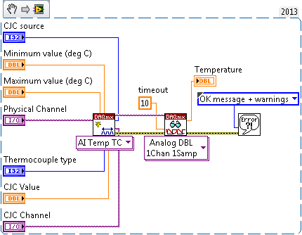
The inputs to the NI-DAQmx Create Virtual Channel function differ for each instance of the function. However, certain inputs are common to most, if not all, of the function's instances. For example, an input is required to specify the physical channels (analog input and analog output), lines (digital), or counter that the virtual channel(s) will use. Additionally, analog input, analog output, and counter operations use minimum value and maximum value inputs to configure and optimize the measurements and generations based on the minimum and maximum expected values of the signals. Furthermore, a custom scale can be applied to many types of virtual channels. In the following LabVIEW block diagram, the NI-DAQmx Create Virtual Channel VI is used to create a thermocouple virtual channel.
Creating a Channel in .NET
Most of the classes in the NI-DAQmx .NET library cannot be instantiated directly. These classes are used as subobjects of the class.
These classes contain properties that are specific to a particular type of channel. For example, properties such as Count are only applicable to counters and are only available on the CIChannel and COChannel classes. You can associate the following types of channels with a in the NI-DAQmx .NET class library:
Analog input channels— class
Analog output channels— class
Digital input channels— class
Digital output channels— class
Counter input channels— class
Counter output channels— class
The Task class has a channel collection property for each of six types of channels— , , , , , and . To create a channel, you can use one of the many create channel methods on the channel collections.
After instanting a new Task object, creating and assigning an AIChannel object is done by calling the appropriate member function in the Channel class. The following snippet creates a simple analog input voltage channel:
"dev1/ai1", //The physical name of the channel
"myChannel", //The name to associate with this channel
AITerminalConfiguration.Differential, //Differential wiring
AIVoltageUnits.Volts //Use volts
);
Creating a Task in C/C++
Use the DAQmxCreateTask() function to create a task and DAQmxCreateAIVoltageChan() to create an analog input voltage channel. For information on creating channels for different measurement types, see the NI-DAQmx C Reference Help. Below is a snippet of how to use the two functions:
TaskHandle taskHandle=0;
char chan[256] = "Dev1/ai0";
float64 min = -10, max = 10;DAQmxCreateTask("",&taskHandle);
DAQmxCreateAIVoltageChan(taskHandle ,chan ,"", DAQmx_Val_Cfg_Default, min, max, DAQmx_Val_Volts, NULL);
Examples to Examine:
| LabVIEW | Digital - Finite Output.vi |
|---|---|
| Thermocouple - Continuous Input.vi | |
| CVI | Write Dig Port |
| Cont Thrmcpl Samples-Int Clk | |
| .NET | WriteDigPort |
| ContAcqThermocoupleSamples_IntClk |
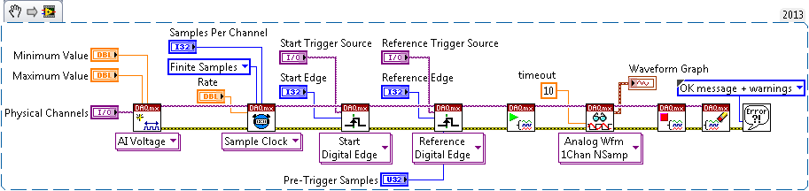
Many data acquisition applications require synchronization of different functional areas of a single device (e.g. analog output and counters). Others require multiple devices to be synchronized. To achieve this synchronization, trigger signals must be routed between the different functional areas of a single device and between multiple devices. NI-DAQmx automatically performs this routing. When using the NI-DAQmx Trigger function, all valid trigger signals are available as the source input to the function. For example, in the following NI-DAQmx Trigger VI, the start trigger signal for Device 2 is available as the source of the start trigger for Device 1 without any explicit routing being performed.
Creating a Trigger in .NET
After creating a Task object and a Channel, you can add a trigger to the task by calling the methods within the Task.Triggers collection. The following code snippet creates a Digital Edge Start Trigger:
DigitalEdgeStartTriggerEdge triggerEdge = DigitalEdgeStartTriggerEdge.Rising;
analogInTask.AIChannels.CreateVoltageChannel( . );
analogInTask.Triggers.StartTrigger.ConfigureDigitalEdgeTrigger("PFI0", triggerEdge);
Based on the parameters sent to the ConfigureDigitalEdgeTrigger function the device will look to in an internal or external line for a rising or falling digital edge before it begins to acquire data. The snippet above configures the device to look on PFI 0 for a rising digital edge trigger.
Creating a Trigger in C/C++
Use the DAQmxCfgDigEdgeStartTrig() function to create a digital edge start trigger. For information on creating different triggers, see the NI-DAQmx C Reference Help. Below is a snippet that shows how to use the function for a digital start trigger coming in on PFI0 and looking for a rising edge on that line.
char startTrigger[256] = "Dev1/PFI0";
int startEdge = 0; // rising edgeDAQmxCreateTask("",&taskHandle));
DAQmxCreateAIVoltageChan(taskHandle, chan, "", DAQmx_Val_Cfg_Default, min, max, DAQmx_Val_Volts, NULL);
DAQmxCfgDigEdgeStartTrig(taskHandle, startTrigger, startEdge);
The Timing and Synchronization Features of NI-DAQmx document contains additional information concerning the use of the NI-DAQmx Trigger function to perform synchronization with NI-DAQmx.
Examples to Examine:
| LabVIEW | Voltage - Finite Input.vi |
|---|---|
| Voltage - Continuous Input.vi | |
| CVI | Acq-Int Clk-Dig Start&Ref |
| Cont Acq-Int Clk-Anlg Start | |
| .NET | AcqVoltageSamples_IntClkDigStartAndRef |
| ContAcqVoltageSamples_IntClkAnalogStart |